CONCEPT

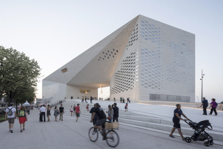
MECA Cultural Centre by BIG
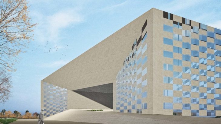
This project demonstrates the final study outcome of the MAA01 program (2021-2022)’s Computational Design seminar, using the façade of the MECA Cultural Centre by Bjarke Ingels Group. The concept of the parametric design is to diminish the noise pollution near the building which is mostly caused by traffic. The parametric panels which are set as the window openings change the width based on the distance between the noise and the façade. As the noise gets closer to the building the panels get bigger so the window opening become smaller, less noise enters the building.
GRASSHOPPER SCRIPT

PSEUDOCODE

- Choose the surfaces from the rhino file and put them in the grasshopper file
- Merge the surfaces so that they can be controlled together
- Use the “Isotrim” command to create the grids on the surfaces
- Use the “Divide Domain2” command to determine how many segments should be created in the U and V direction
- Use the “Partition List” command to create branches for each column
- “Cull Index” to exclude the first and last column from each of the surfaces.
- To determine the last column, we include the expression “x-1” – if we manually enter 9 the code is not parametric & to include the first, we input “0” as a panel
- Using the chessboard code select every alternating rectangle vertically and horizontally which will be the window openings we will be adjusting depending on the attractor point.
- Using the “Tree Statistics” command find the paths of the branches
- “Dispatch” the paths to select the alternating columns
- Retrieve the branches from List A and B
- “Dispatch” again to select the alternating rows for both lists from branches
- Merge the data from the final dispatch to create a chessboard module
- One of the merged data from here becomes the solid surface which we will only extrude perpendicular to the surface
- The other one is the window panel which is reacting to the attractor point
- The window panels will be scaled by keeping the height same and only changing the width of the segments
- To be able to scale the segments we have to evaluate surface and find the frames which becomes the plane we are scaling
- In order to set the scale factor as a parametric value we set an attractor point and we will amplitude the width depending on the attractor point.
- To find the vector value for the amplitude we use “Vector 2PT” to find the vector between the centre of each rectangle and the attractor point.
- For the “Amplitude” which is the scale factor we first make the “Distance” between the attractor point and the centre of each square. As the value here is too high we have to remap the values so we “Bound” to find min and max value as the source and “Construct Domain” for our target value.
- The “Amplitude” command is used as the scale factor on the “X axis”
- We need to extrude the rectangle so they become a solid surface. To extrude perpendicularly we have to “Evaluate Surface”
- The “Evaluate Surface” command requires a “UV Point” input which is found using the “Surface Closest Point” in which the centre of each rectangle is used as the point.
- To “Extrude” we use the data from the “Scale NU” as the geometry and for the direction we use “Amplitude” in order to set a value with a vector.
- We build the solid facades on grasshopper (extruding the surfaces) too so that it will be easier. We internalised the data so the model can be opened with the grasshopper script only. The facades don’t require any parametric features.
ANIMATION
